Click to buy PRO-T527 Expanding Board now>>


Main hardware parameters | |
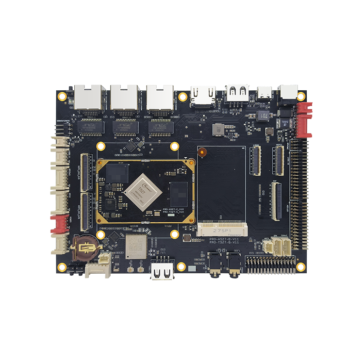
Size | 155 mm L * 115 mm W * 14 mm H |
CPU | T527 8 core A55 frequency 2G |
GPU | G57 MC01 |
Memory | LPDDR4 standard 2GB/4GB optional 1GB |
Storage device | EMMC 5.1 standard 8GB/32GB optional 16GB/64GB |
Power management | AXP717+AXP323 |
Working voltage | 12V 2A or above |
Support system | Andriod 13 |
Operating temperature | -10 to + 75 degrees |
Common interface of motherboard | |
USB interface | 4-way USB port (4-way external, 1-way plug-in) J9 for Device |
Camera interface | 2-way 2+4LANE MIPI camera interface, built-in ISP up to 800W |
serial port | 8-channel UART serial port (one is debug, can be changed to ordinary serial port) |
SPI interface | 2 External SPI |
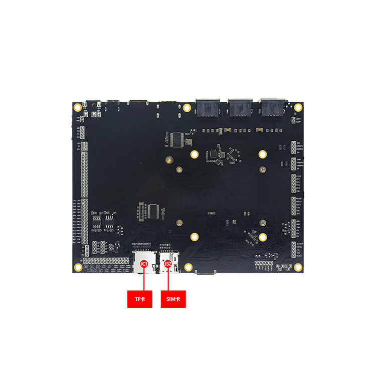
4G interface | Access to the Internet with 4G module (USB) |
Voice input | 2 audio inputs, 1 microphone + 1 LANE IN |
Voice output | 2-channel headset output + 1-way speaker output 5W/8 |
TF card | Support for TF card |
MIPI display | 2-way MIPI display output, single maximum 1920x1080 |
LVDS display | Double 8 LVDS output maximum 1920x1080 |
EDP display | 1-way eDP display output highest 1920x1080 |
HDMI display | 1 HDMI HD output up to 4K 60 fps |
Ethernet | 3-Way Gigabit Ethernet RGMII 0 + RGMII 1 + PCIE |
WIFI | 1-Way WIFI 6 (VS 2275 S) |
Bluetooth | 1 way 5.3Bluetooth + BLE (VS2275S) |
I2C | 5-way I2C interface |
PWM | 2 PWM outputs |
can interface | 2-way CAN interface |
Other extended interfaces | 5 available GPIO |
ADC interface | 26 ADC interface |
Indicator light | 1-way GPIO controllable indicator interface |
RTC real-time clock | External button battery power down time saved (independent 8563) Power consumption is less than 1uA |
System upgrade | Support for local USB upgrades |
PRO-T527 Features and Driver Support List | ||
Android 13.0 | Remarks | |
Hardware function | ||
HDMI (native) | √ | |
HDMI (LT8912,DSI0 to HDMI) | √ | |
MIPI display screen (5.5in 720x1280 plus touch assembly) | √ | |
MIPI display screen (5.5in 1080x1920 plus touch assembly) | √ | |
MIPI display screen (7-inch 1024x600 plus touch assembly) | √ | |
MIPI display screen (7-inch 1200x1920 plus touch assembly) | √ | |
MIPI display screen (8-inch 800x1280 plus touch assembly) | √ | |
MIPI display screen (10.1in 800x1280 plus touch assembly) | √ | |
MIPI display screen (10.1in 1920x1200 plus touch assembly) | √ | |
LVDS display screen (10.1in 1024x600 plus touch assembly) | √ | |
LVDS display screen (10.1in 1280x800 plus touch assembly) | √ | |
Dual LVDS Display (21.5 "1920 x 1080) | √ | |
EDP display screen (13.3in 1920x1080 plus touch assembly) | √ | |
LED lamp (enter the system breathing light) | √ | |
Fan | √ | CPU 60 degrees on |
RTC (plug-in HYM8563, power-off time saved) | √ | |
Loudspeaker (5W/8 can be connected to the backplane to play sound) | √ | |
Headset (with headset detection function) | √ | |
Microphone input | √ | |
Linein input | √ | |
WIFI(vs2275s) | √ | |
Bluetooth (vs 2275 s) | √ | |
USB OTG(Type-C) | √ | |
USB HUB 1x4port | √ | |
Gigabit Ethernet 0 (YT8531 C-CA LED indicator and iperf test) | √ | |
Gigabit Ethernet 1 (YT8531 C-CA LED indicator and iperf test) | √ | |
PCIE to Gigabit Ethernet 2 (RTL 8111 HS LED and iperf test) | √ | |
Debug serial port (can send and receive, can also be used as ordinary serial port) | √ | |
Serial port (can send and receive data normally) | √ | |
TF card (test maximum 128G TF card to transfer files to each other) | √ | |
Keys (reset key, upgrade key, PWR key) | √ | |
4G newsletter (move away from EC20, EC200 series) | √ | |
26-channel ADC pin output data read | √ | |
SPI 0/2 Pin Out | √ | |
I2C pin out | √ | |
GPIO | √ | |
CAN | √ | |
4-channel MIPI camera interface | √ | |
Bus driver | ||
PCIE driver | √ | |
SPI driver | √ | |
ADC driver | √ | |
I2C driver | √ | |
PWM driver | √ | |
SDIO driver | √ | |
GPIO driver | √ | |
USB driver | √ | |
Project | Minimum | Typical | Maximum | |
Power supply parameters | Voltage | 7.5V | 12V | 15V |
Ripple | -- | 50mV | 120mV | |
Electric current | 172mA | -- | -- | |
Power supply current (no other peripherals are connected) | Power-on current | 175mA | 239mA | 496mA |
Play sound | 182mA | 225mA | 375mA | |
Environment | Relative humidity | -- | 65% | 75% |
Operating temperature | -10 ℃ | -- | 75 ℃ | |
Storage temperature | -30 ℃ | -0 ℃ | 100 ℃ | |
Click to buy PRO-T527 Expanding Board now>>
Main hardware parameters | |
Size | 155 mm L * 115 mm W * 14 mm H |
CPU | T527 8 core A55 frequency 2G |
GPU | G57 MC01 |
Memory | LPDDR4 standard 2GB/4GB optional 1GB |
Storage device | EMMC 5.1 standard 8GB/32GB optional 16GB/64GB |
Power management | AXP717+AXP323 |
Working voltage | 12V 2A or above |
Support system | Andriod 13 |
Operating temperature | -10 to + 75 degrees |
Common interface of motherboard | |
USB interface | 4-way USB port (4-way external, 1-way plug-in) J9 for Device |
Camera interface | 2-way 2+4LANE MIPI camera interface, built-in ISP up to 800W |
serial port | 8-channel UART serial port (one is debug, can be changed to ordinary serial port) |
SPI interface | 2 External SPI |
4G interface | Access to the Internet with 4G module (USB) |
Voice input | 2 audio inputs, 1 microphone + 1 LANE IN |
Voice output | 2-channel headset output + 1-way speaker output 5W/8 |
TF card | Support for TF card |
MIPI display | 2-way MIPI display output, single maximum 1920x1080 |
LVDS display | Double 8 LVDS output maximum 1920x1080 |
EDP display | 1-way eDP display output highest 1920x1080 |
HDMI display | 1 HDMI HD output up to 4K 60 fps |
Ethernet | 3-Way Gigabit Ethernet RGMII 0 + RGMII 1 + PCIE |
WIFI | 1-Way WIFI 6 (VS 2275 S) |
Bluetooth | 1 way 5.3Bluetooth + BLE (VS2275S) |
I2C | 5-way I2C interface |
PWM | 2 PWM outputs |
can interface | 2-way CAN interface |
Other extended interfaces | 5 available GPIO |
ADC interface | 26 ADC interface |
Indicator light | 1-way GPIO controllable indicator interface |
RTC real-time clock | External button battery power down time saved (independent 8563) Power consumption is less than 1uA |
System upgrade | Support for local USB upgrades |
PRO-T527 Features and Driver Support List | ||
Android 13.0 | Remarks | |
Hardware function | ||
HDMI (native) | √ | |
HDMI (LT8912,DSI0 to HDMI) | √ | |
MIPI display screen (5.5in 720x1280 plus touch assembly) | √ | |
MIPI display screen (5.5in 1080x1920 plus touch assembly) | √ | |
MIPI display screen (7-inch 1024x600 plus touch assembly) | √ | |
MIPI display screen (7-inch 1200x1920 plus touch assembly) | √ | |
MIPI display screen (8-inch 800x1280 plus touch assembly) | √ | |
MIPI display screen (10.1in 800x1280 plus touch assembly) | √ | |
MIPI display screen (10.1in 1920x1200 plus touch assembly) | √ | |
LVDS display screen (10.1in 1024x600 plus touch assembly) | √ | |
LVDS display screen (10.1in 1280x800 plus touch assembly) | √ | |
Dual LVDS Display (21.5 "1920 x 1080) | √ | |
EDP display screen (13.3in 1920x1080 plus touch assembly) | √ | |
LED lamp (enter the system breathing light) | √ | |
Fan | √ | CPU 60 degrees on |
RTC (plug-in HYM8563, power-off time saved) | √ | |
Loudspeaker (5W/8 can be connected to the backplane to play sound) | √ | |
Headset (with headset detection function) | √ | |
Microphone input | √ | |
Linein input | √ | |
WIFI(vs2275s) | √ | |
Bluetooth (vs 2275 s) | √ | |
USB OTG(Type-C) | √ | |
USB HUB 1x4port | √ | |
Gigabit Ethernet 0 (YT8531 C-CA LED indicator and iperf test) | √ | |
Gigabit Ethernet 1 (YT8531 C-CA LED indicator and iperf test) | √ | |
PCIE to Gigabit Ethernet 2 (RTL 8111 HS LED and iperf test) | √ | |
Debug serial port (can send and receive, can also be used as ordinary serial port) | √ | |
Serial port (can send and receive data normally) | √ | |
TF card (test maximum 128G TF card to transfer files to each other) | √ | |
Keys (reset key, upgrade key, PWR key) | √ | |
4G newsletter (move away from EC20, EC200 series) | √ | |
26-channel ADC pin output data read | √ | |
SPI 0/2 Pin Out | √ | |
I2C pin out | √ | |
GPIO | √ | |
CAN | √ | |
4-channel MIPI camera interface | √ | |
Bus driver | ||
PCIE driver | √ | |
SPI driver | √ | |
ADC driver | √ | |
I2C driver | √ | |
PWM driver | √ | |
SDIO driver | √ | |
GPIO driver | √ | |
USB driver | √ | |
Project | Minimum | Typical | Maximum | |
Power supply parameters | Voltage | 7.5V | 12V | 15V |
Ripple | -- | 50mV | 120mV | |
Electric current | 172mA | -- | -- | |
Power supply current (no other peripherals are connected) | Power-on current | 175mA | 239mA | 496mA |
Play sound | 182mA | 225mA | 375mA | |
Environment | Relative humidity | -- | 65% | 75% |
Operating temperature | -10 ℃ | -- | 75 ℃ | |
Storage temperature | -30 ℃ | -0 ℃ | 100 ℃ | |